Engineer:Tim Ma Tel:+86 18761599716 E-mail: tim.ma@email.acrel.cn
Jiangsu Acrel Electrical MFG Co. Ltd
Abstract: With the continuous development of the social economy, the power system is moving towards the direction of high voltage and high capacity. New technologies and equipment of the power system emerge in an endless stream, and the power transmission capacity continues to improve.However, the high-voltage power load carried by high-voltage electrical equipment also makes its own temperature rise the culprit that threatens the stability of the power grid. Equipment temperature has become an important parameter for the stable operation of power transmission equipment in the current power grid.Based on the reasons for the temperature rise of high-voltage electrical equipment, this article analyzes the structure and application of the wireless temperature measurement system, analyzes the advantages and disadvantages of its application, and provides application examples to provide reference for the stable operation and development of our country's power system.
Keyword: Wireless temperature measurement system; high voltage electrical equipment; advantages and disadvantages
The high-voltage electrical equipment in our country's power system has a variety of connection points, such as isolated switch joints, busbar nodes, etc. Due to the quality problems in the manufacturing or safety process, many devices will have poor contact problems and a large resistance will be generated during use, resulting in temperature rise problems.
1. Reasons for temperature rise of high-voltage electrical equipment
The application of the temperature measurement system is inseparable from the analysis of the cause of the temperature rise problem.The first is the quality and installation problems of high-voltage electrical equipment itself, especially at the joints of equipment bolts.Whether the connection points meet the standards, and whether the tightness meets the standards all affect the strength of the resistance.Many equipment connections will have uneven and rough problems during installation. Inadequate grinding will also lead to increased resistance and poor contact, which will affect the use of equipment and make the temperature rise problem obvious.Second, careless protection during the transportation of high-voltage electrical equipment will cause bumps, resulting in deformation of connection points or key parts, thereby resulting in poor contact.Third, the metal surface of high-voltage electrical equipment itself is prone to corrosion or oxidation reactions, and problems on the surface of the equipment will also affect the contact of the equipment. The poor working environment of some electrical equipment, such as high temperature, rain, snow, and strong wind, will accelerate the aging of the equipment itself, causing serious temperature rise problems.Fourth, external factors affect poor contact at the connection of the equipment. Many equipment operating sites are relatively complicated, and various links such as equipment installation, use, and maintenance are also prone to mistakes, resulting in poor contact of many cable connectors and isolating switches, and serious temperature rise problems.Fifth, the equipment is under high load pressure for a long time. The high-voltage electrical equipment itself carries the transmission and application of high-voltage electricity. Once the current is too large and exceeds the carrying capacity of the equipment, coupled with the thermal effect of the current itself, the temperature of the equipment will rise rapidly.
In actual equipment operation, the above five problems will occur at the joints of circuit breakers, dis-connectors, cable joints, bushings and bus bars,etc.These areas have many faults and are prone to temperature rise problems. In daily inspection and maintenance, the staff should focus on inspection and maintenance.During the inspection of the equipment, the temperature measurement of the device can not only grasp the status of the device during use, but also timely detect the excessive heat generated by poor contact or excessive load.In the charged state, due to the influence of current and heat, it is normal for the internal temperature to be higher than the outside world, but the heat change due to the failure of the equipment itself or excessive load needs to be closely monitored. This temperature rise problem will aggravate the aging of the equipment, thereby reducing the life of the equipment, and may even cause the equipment to burn out. Therefore, it is very necessary to apply a temperature measurement system to high-voltage electrical equipment.
In China, the most used temperature measurement methods for high-voltage power equipment are temperature display wax chip method, infrared temperature measurement method, optical fiber temperature measurement method and wireless temperature measurement system.Both the temperature display method and the infrared thermometer are manually operated, and the data cannot be collected in real time. Through optical fiber measurement, real-time measurement results can be obtained. However, in the case of high and low voltage, it cannot completely isolate environmental factors, and cannot meet the requirements of electrical instrumentation specifications for high-voltage instruments. Moreover, when installing in the cabinet, there are also great obstacles to its installation due to problems such as the optical fiber is not resistant to high temperature and the wiring is difficult.The existing wireless temperature measurement technology mainly relies on the current wireless transmission mode to overcome the connection and attachment problems of the primary and secondary loops, thereby improving the safety of high-voltage power use.
2. Analysis of wireless temperature measurement system structure and equipment application
The composition of the wireless temperature measurement system can be divided into the temperature sensor part and the temperature monitoring result display and analysis part, as well as the hardware and software of the system.The structure of the wireless temperature measurement system for high-voltage power equipment as shown in Figure 1 is usually installed with temperature sensors at the junction of switch cabinets, cable joints, fuses, etc. In order to ensure the accuracy of the measurement, the sensor is usually at the same voltage position as the test object, and then the collected signal is transmitted and displayed using wireless technology.In order to ensure the safety of temperature measurement, the high voltage and low voltage working parts are insulated to prevent leakage and other accidents.Usually, multiple channels are provided on the external surface of the working equipment for real-time monitoring and data processing of multiple locations. Then the data received by the receiver is transmitted to the computer through the serial or parallel port, and analyzed and processed by the pre-programmed program.
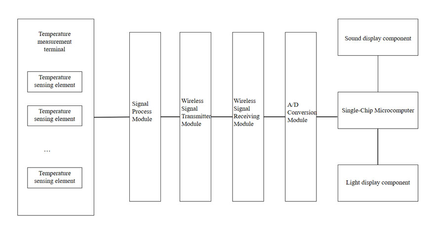
Figure 1 Schematic diagram of the structure of the wireless temperature measurement system for high-voltage power equipment
2.1 Temperature sensor
The function of the temperature sensor is to convert the temperature signal into an electrical signal. Usually, a Pt100 thermocouple meter is used, and its measurement accuracy can reach 0.1 degrees Celsius. A zero-flux miniature current sensor can also be used, which also has high application value.Technically speaking, the magnetic sensor chooses low-loss Permalloy as the iron core, and uses special negative pressure technology and protection means to realize automatic compensation for the iron core, so that the iron core is in the ideal working condition of zero magnetic flux .In addition to the temperature measuring device, the wireless temperature sensor also includes a power supply, a measurement circuit, a logic control circuit and a radio communication circuit at a specific frequency.In order to adapt to higher working conditions, it is generally packaged in high-temperature, high-pressure heat-shrinkable tubing, and has certain waterproof and dust-proof properties to ensure long-term use.Since the working area of wireless temperature measuring equipment is usually small, its size should be reduced as much as possible to meet the working conditions during use.When using a temperature sensor, heat-resistant gluing wire or gluing technology can be used to combine the heat-sensitive element with the surface of the object, but care should be taken to keep the contact points close to reduce measurement errors.The wireless temperature sensor should have a wide linear working range. Usually, a temperature sensing element of -55~130 degrees Celsius is selected, and the temperature sensor is selected according to the requirements of measurement accuracy and measurement error under various working conditions.
2.2 Wireless Temperature Detector
The wireless temperature detector system has multiple receiving channels, which can process and display multiple different measuring points in real time.There are judgment and fault handling functions in the wireless temperature detector. A safety zone is set in advance by the staff, and the collected information is compared with the set threshold by the wireless temperature detector. If the temperature exceeds the threshold, it will enter the fault processing module and output the warning text, and output a set of high and low levels to start the alarm signal and sound.In addition to the basic detection and alarm functions, the wireless temperature detector also has the ability to transmit information. It can be connected to a computer through a data line or a serial/parallel port communication chip, and employees can monitor multiple switches and contact parts in real time, and control their operating status, so as to discover existing safety problems in time.
2.3 Real-time temperature monitoring system
Compared with the above-mentioned hardware facilities such as sensors and detectors, the real-time temperature monitoring system is more inclined to the software system in the wireless temperature measurement system.The real-time temperature monitoring system is the integration of the overall wireless temperature measurement hardware operation, data processing, signal collection and other functions. It communicates with the staff through the client interface and uploads and issues instructions.In order to reduce the labor intensity of operators, technical workers have developed a real-time temperature monitoring system that meets the above description, so as to analyze and process the temperature measurement results of the hardware part.The real-time temperature monitoring system has the functions of temperature display, data storage, historical data analysis and comparison, fault warning, fault analysis, equipment operation status analysis, etc., and it can integrate and complement the functions of the hardware part.In the design of the real-time temperature monitoring system, some modular design methods can be used for the redundant data processing work, and each module unit is decomposed according to the function, and the data is stored and processed by category. This modular design method can make the real-time temperature monitoring system have higher applicability and safety. The real-time temperature monitoring system can assist technical workers to collect, extract, compare and analyze a large amount of data, and can report various abnormal conditions in real time according to different temperatures of different equipment to ensure the normal operation of various devices.At the same time, the real-time temperature monitoring system also has good mathematical operation and visualization performance, which can display the data of a certain period as a chart and mark the data to facilitate later maintenance.
3. Advantages and disadvantages of wireless temperature measurement system applied to high-voltage electrical equipment
3.1 Technical advantages of wireless temperature measurement system applied in electrical equipment
With the advancement of science and technology, the wireless temperature measurement system has undergone numerous upgrades and updates, its performance has become stronger and stronger, and the temperature monitoring has become more and more accurate.The current power construction requires the wireless temperature measurement system to be more and more real-time and accurate, especially for high-voltage electrical equipment. The wireless temperature measurement system is also constantly adjusted with the application of high-voltage electrical equipment.In terms of signal reception, the wireless temperature measurement system extends a higher signal frequency based on the characteristics of high-voltage electrical equipment, which has good stability and is not easily disturbed by external factors.Wireless communication technology is used in signal transmission, which is relatively simple, low energy consumption and cost, and can be analyzed and processed according to the received data, and the working status of the instrument can be monitored in real time without being affected by the weather conditional restrictions.The temperature of the instrument can be monitored in real time to avoid missed detection. At the same time, the over-temperature alarm of the device can be set according to the user's needs, and the operator can be reminded of the specific equipment location through sound and signal.
3.2 Insufficient application of wireless temperature measurement system in electrical equipment
The temperature measurement of high-voltage electrical equipment using the wireless temperature measurement system reduces the inspection work intensity of substation operators and improves the safety performance of the equipment at the same time.However, there are also certain shortcomings in the wireless temperature measurement system in actual use.First of all, the wireless temperature measurement system is an active technology, which requires a built-in battery for power supply. When the battery is exhausted, the wireless temperature measurement system will automatically shut down, and the staff cannot see the temperature of the device, and can only restore the connection by disconnecting the line to replace the battery,as a result, the number of switching operations and unplanned power outages in the substation is greatly increased.In order to solve this problem, we can improve the technology, replace the built-in battery with a passive power supply, and use the electromagnetic wave generated by the fixed point current as the power, so that the reliability of the whole system has been improved.Secondly, some temperature control indicators of the power supply device often fail in practical applications. It is preliminarily judged that the battery of the wireless temperature measurement sensor is insufficient. After the power failure and replacement of the wireless temperature measurement sensor, this phenomenon still exists.In this case, it is necessary to detect the site, debug the installation of the receiving end, shorten the distance between the temperature measurement point and the wireless temperature measurement system, and avoid this situation.In addition, the wireless temperature sensor with its own active technology cannot replace the battery. If it detects that the battery is not enough, the wireless sensor must be replaced. This will not only increase the maintenance cost of the instrument, but also cause resource consumption of the equipment.
4. Application examples of wireless temperature measurement system
Compared with foreign wireless temperature measurement system technology, the development of domestic temperature measurement technology is relatively lagging behind, but due to the continuous attention of the domestic industry in recent years, the investment, manpower and material resources in this field have been improved. In the power industry, there are many auxiliary equipment devices, especially monitoring equipment for power operation.That is, when the line runs to a certain load or high temperature, the device will automatically stop power supply to avoid accidents.These practical new products are mostly used in high-voltage electrical equipment, and their interfaces are pre-installed and cannot be replaced.Although it will reduce the generation of resistance to a certain extent, it is easy to cause failure due to long-term work, which will increase the resistance of the device itself and increase the heat during operation.So for a long time, it is easy to cause safety accidents, endangering the health of people's personal and property. In response to this situation, some domestic companies have applied wireless temperature measurement technology to power production.With the popularity of this technology, it is now widely used not only in the power industry, but also in other industries with temperature rise problems.

5. Application scenarios
The electrical contact online temperature measuring device is suitable for temperature monitoring of cable joints in high and low voltage switch cabinets, circuit breaker contacts, knife switches, high-voltage cable intermediate heads, dry-type transformers, low-voltage and high-current equipment. It can prevent potential safety hazards caused by excessive contact resistance and heating due to oxidation, looseness, dust and other factors during operation, thereby improving equipment safety, timely, continuously and accurately reflecting equipment operating status, and reducing equipment accident rates.
6. System hardware configuration
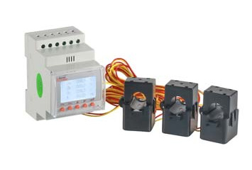
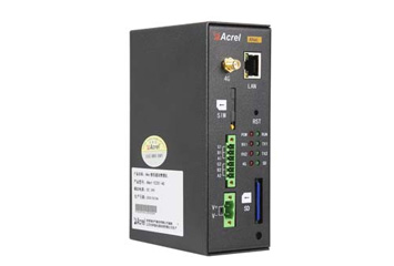
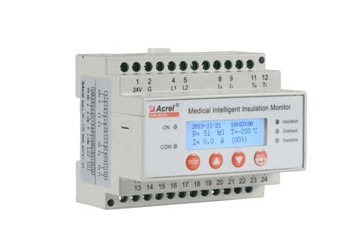
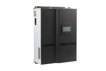
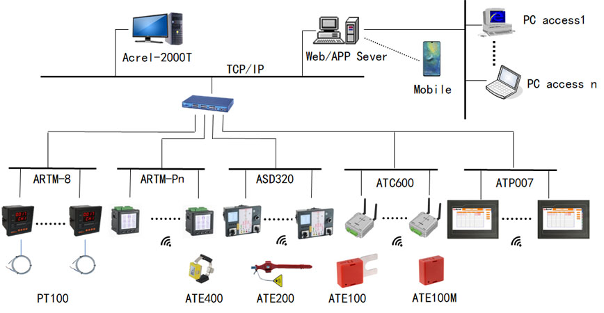
The temperature online monitoring system is mainly composed of a temperature sensor and a temperature acquisition/display unit at the equipment layer, an edge computing gateway at the communication layer, and a temperature measurement system host at the station control layer to realize online temperature monitoring of key electrical parts of the power transformation and distribution system.
Name | Appearance | Type | Parameter Description |
System configuration software | 
| Acrel-2000/T | Hardware: memory 4G, hard disk 500G, Ethernet port.
Display: 21 inches, resolution 1280*1024.
Operating system: Windows7 64-bit Simplified Chinese Ultimate.
Database system: Microsoft SQL Server 2008 R2.
Communication protocol: IEC 60870-5-103, IEC60870-5-104,Modbus RTU, Modbus TCP and other international standard communication protocols |
Smart communication management machine | 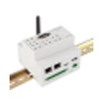
| Anet-2E4SM | Universal gateway, 2-way network port, 4-way RS485, optional 1-way LORA, live alarm function, support 485, 4G slave module expansion |
Centralized collection equipment for wireless temperature measurement | 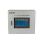
| Acrel-2000T/A | Wall mounted
One standard 485 interface, one Ethernet port
Built-in buzzer alarm
Cabinet size 480*420*200 (unit mm) |
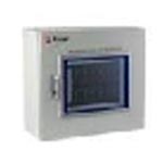
| Acrel-2000T/B | Hardware: memory 4G, hard disk 128G, Ethernet port
Display: 12 inches, resolution 800*600
Operating system: Windows7
Database system: Microsoft SQL Server 2008 R2
Optional Web Platform/APP Server
Cabinet size is 480*420*200 (unit: mm) |
Display terminal | 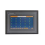
| ATP007/
ATP010 | DC24V power supply; one way uplink RS485 interface; one way downlink RS485 interface;
Receive 20 pcs ATC200/1 pc ATC400/
1 pc ATC450-C. |
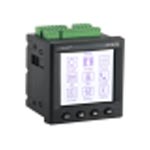
| ARTM-Pn | Surface frame 96*96*17mm, depth 65mm; bore diameter 92*92mm;
AC85-265V or DC100-300V power supply;
One way uplink RS485 interface, Modbus protocol;
Receive 60 pcs ATE100/200/300/400; match ATC200/300/450. |
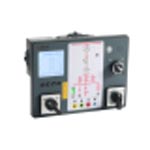
| ASD320/
ASD300 | Surface frame 237.5*177.5*15.3mm, depth 67mm; bore diameter 220*165mm;
AC85-265V or DC100-300V power supply;
One way uplink RS485 interface, Modbus protocol;
Receive 12 pcs ATE100/200/300/400; match ATC200/300/450 |
Intelligent temperature inspection instrument | 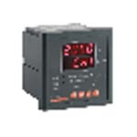
| ARTM-8 | Bore diameter 88*88mm embedded installation;
AC85-265V or DC100-300V power supply;
One way uplink RS485 interface, Modbus protocol;
Can be connected to 8-way PT100 sensors, suitable for temperature measurement of low-voltage switch-gear electrical contacts, transformer windings, click windings, etc.; |
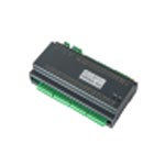
| ARTM-24 | 35mm din rail installation;
AC85-265V or DC100-300V power supply;
One way uplink RS485 interface, Modbus protocol;
24 channels of NTC or PT100, 1 channel of temperature and humidity measurement, 2 channels of relay alarm output, used for temperature measurement of low-voltage electrical contacts, transformer windings, click windings and other places; |
Wireless transceiver | 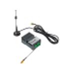
| ATC450-C | Receive data of 60 pcs ATE100/ATE100M/ATE200/ATC400/ ATE100P/ATE200P sensor |
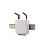
| ATC600 | ATC600 has two specifications: ATC600-C can receive the data of 240 pcs ATE100/ATE100M/ATE200/ATC400/ ATE100P/ATE200P sensor. ATC600-Z does relay transparent transmission. |
Battery Type Wireless Temperature Sensor | 
| ATE100M | Battery powered,service life ≥ 5 years; -50°C~+125°C; accuracy ±1°C; 470MHz, open distance 150 meters; 32.4*32.4*16mm (length*width*height) |

| ATE200 | Battery powered, service life ≥ 5 years; -50°C~+125°C; accuracy ±1°C; 470MHz, open distance 150 meters; 35*35*17mm, L=330mm (length*width*height, three-color strap). |
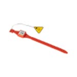
| ATE200P | Battery powered, service life ≥ 5 years; -50°C~+125°C; accuracy ±1°C; 470MHz, open distance 150 meters, protection class IP68; 35*35*17mm, L=330mm (length*width*height, three-color strap). |
CT power-taking wireless temperature sensor | 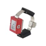
| ATE400 | CT induction power supply, starting current ≥5A; -50℃~+125℃; accuracy ±1℃; 470MHz, open distance 150 meters; fixed alloy sheet, power supply; three-color shell; 25.82*20.42*12.8mm (length*width *high). |
Wired temperature sensor | 
| PT100 | When used for low-voltage contact temperature measurement, please contact the supplier for specific package, accuracy, wire system, wire material, and wire length;
When used for temperature measurement of transformer and motor windings, it is recommended to pre-embed Pt100 inside the transformer or motor |
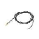
| NTC | When used for low-voltage contact temperature measurement, please contact the supplier for specific package, accuracy, wire system, wire material, and wire length;
When used for transformer and motor winding temperature measurement, it is recommended that the transformer or motor be pre-embedded |
7. Conclusion
Due to the continuous development of sensors, wireless data communication, data mining and other technologies, the real-time monitoring system of high-voltage electrical temperature will become more scientific. With the application and popularization of the wireless temperature measurement system, our country's power industry is also more stable and safe, and its technological progress has contributed to the development of our country.
References:
[1] Acrel Enterprise Microgrid Design and Application Manual. Version 2022.05
 English
